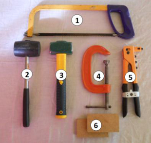
It is suggested that the following hand tools are sourced prior to carrying out the installation process.
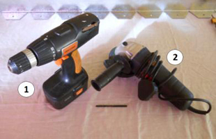
It is suggested that the following power tools are sourced prior to carrying out the installation process.
To avoid potential injury from handling the Irandipro units it is suggested that the system is handled with industrial grade safety gloves.
The use and handling of all suggested hand and power tools should be in line with current industry best practice and Manufacturers specific guidance.
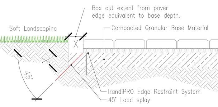
The depth of the box cut and associated formation level will be subject to the strength of the subgrade. The sub-grade strength is measured by means of the California Bearing Ratio or CBR as its more commonly referred to.
Once the CBR of the formation is known, a suitable depth of base material can be determined and a box cut carried out to suit the required depth of the base. Any soft spots found in the subgrade should be removed and the area filled with suitable capping material.
Particular care must be taken to ensure that the width of the box cut is sufficiently far from the edge of the pavers to enable an equivalent length of base material depth can be installed. This approach ensures that any load on the edge of the pavers is transmitted to the subgrade via base material.
Preparation of the base is an incredibly important aspect of the overall pavement installation and taking the time and effort to ensure it’s installed to the correct line, level and degree of compaction will improve the overall performance of the paved surface.
Compaction of light duty sub-bases are usually carried out with plate compactors and depending on the thickness of the sub-base it should be laid in two or more layers with a lift of between 50 to 75mm.
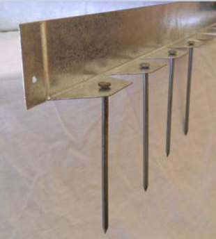
Once the sub-base has been prepared, the IrandiPRO edge rail is set out and nailed to the base using either 150mm wire or 120mm spiral steel nails. The lower leg of the ‘L-Shaped’ rail is to be located beneath the bedding sand and edge course of the paved surface.
The selection of which fixing to utilise is dependent on the type of material the nail is to be driven into. The spiral nail offers a greater bending resistance and is suitable for all applications. In certain instances where the insitu subgrade offers sufficient strength to omit the need for a sub-base, the use of the 150mm round wire nail could be utilised, assuming suitability of the subgrade material.
The spacing of the edge plate fixing pitch is dependent on the use of the paved surface.
In addition to the standard fixing pitch described above, additional fixings to the sub-base should be located in the following instances:
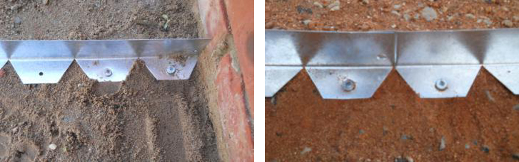
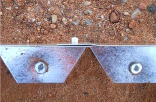
An infinite number of lengths can be joined together to serve any length of edge restraint required by simply utilising a 4.8x12mm aluminium rivet. The end joggle is to wrap around the rear of the unit following on and the rivet head is to be located on the paver side of the edge rail. Nails driven into the sub-base either side of the joint complete the jointing of the two adjacent units.
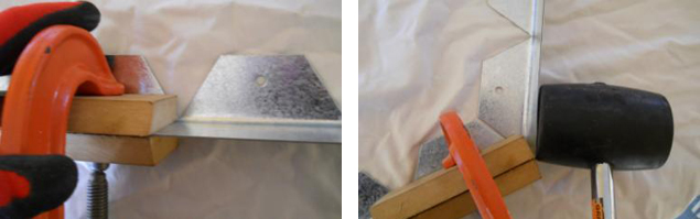
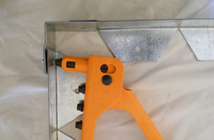
Bends of up to 60° can easily be formed along the edge of the rail at the triangular nodes by clamping the edge rail with 60mm deep wooden blocks along the line of the joint. The rail is then tapped with a rubber mallet until the required deviation is achieved. Should the bend not fall on a node, then the lower leg could be cut to suit the location of the required bend using either a steel saw or angle grinder.
For 90° bends the internal or external fitting should be utilised and is fixed to the preceding and following unit by means of aluminium rivets. For ease of installation the internal or external unit should be fixed to the edge rail and the portion of the edge rail installed butting up to the dwelling or fixed point cut using to size to ensure the correct width of the footway/patio is achieved.
For 90° bends the internal or external fitting should be utilised and is fixed to the preceding and following unit by means of aluminium rivets. For ease of installation the internal or external unit should be fixed to the edge rail and the portion of the edge rail installed butting up to the dwelling or fixed point cut using to size to ensure the correct width of the footway/patio is achieved.
The following procedure should be followed when installing curved sections:
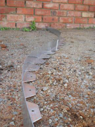
The bedding sand is then installed in the usual manner, but the added benefit of having the edge rail in place means that the screeding rail could be notched and the edge rail used as a guide to ensure the required depth of bedding sand is achieved.
Cover bedding sand when not in use as it is important to work with dry sand and do not attempt to level out any surface irregularities with bedding sand as this will result in an uneven surface.
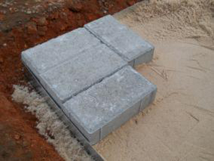
Starting from a permanent edge such as a dwelling or installed IrandiPRO edge rail lay pavers in the normal fashion.
Once all blockwork has been installed and the jointing sand compacted into place, all that remains is to fill the outer edge of the box cut to finish flush with the edge course surface.
The pavement structure is now suitable for trafficking as no curing time is required.